6 min read
How to Integrate S7 PLCs into a PCS 7 Architecture
By: Peter R. Graglia on Dec 12, 2024 5:08:33 PM
Many modern engineering systems are comprised of control systems from various manufacturers, including legacy components and emerging technologies. For example, many OEM-manufactured skids today arrive with included Siemens’ Totally Integrated Automation (TIA) Portal Step 7 controllers, which end users want to integrate to their distributed control system (DCS). This integration can be a challenge, but by taking the proper steps, you can simplify the process and make the most of the robust features found in S7 PLCs and PCS 7.
Integration OptionS
There are many different integration options when interfacing PCS 7 and TIA Portal control systems. The delivered solution will depend on where the customer needs the TIA Portal data to be used, and how the TIA Portal data will be visualized.
When the skid data is to be used for process control in the DCS system, or the customer desires the HMI be visualized following a standard approach, the chosen approach would be to implement processor-to-processor communication, and to use the PCS 7 configuration to provide consistent visualization. In a PCS 7 system, the two main approaches to conducting controller-to-controller communication are by using either Industrial Ethernet (PlantBus) or through PROFINET (an Ethernet-based I/O network). Using Industrial Ethernet, data is sent and received in a peer-to-peer relationship between the PCS 7 controller and the S7 1500 TIA portal controller. Communicating directly between the TIA Portal skid and the PCS 7 Automation Station provides a unified operator interface because the HMI interacts solely with the PCS 7 controller.
When the main objective is to visualize skid data, or to aggregate that data for passing on to a historian, another option is to use the Open Platform Communications Unified Architecture (OPC UA) to communicate from the skid directly to the HMI. The benefits of direct communication with the skid processor are lower PCS 7 configuration effort, and the ability to implement more consistency with skid visualization in the PCS 7 configuration compared to local operator interfaces provided with the skid.
Finally, if a customer is interested in combining the skid control directly in the PCS 7 system, the logic can be migrated into the PCS 7 configuration and the I/O racks may be integrated into the PCS 7 system. This is typically a more significant effort, but can yield a fully customized skid control system matching the DCS’s implementation standards for CMTs, block icons, alarm rationalization, etc.
In this blog, we’ll discuss using send and receive blocks for controller-to-controller communication between a PCS 7 AS410-5H controller and an S7-1500 or S7-1200 system.
12 Steps to Communicate Between TIA Portal and PCS 7 Controllers Using Data Blocks
When using data blocks, you’re taking several bytes from one controller and the corresponding bytes from the other controller, and then mapping their communication into the structure so that both sides are talking the same language. In this example, the data block is defined as three floating point numbers, representing 4 bytes each, so during this process, you are sending those three floating point numbers, representing 12 bytes total. Let’s review step-by-step instructions for how to do this.
Step 1: In TIA Portal, select the communication block “BSEND.”

Step 2: Insert BSEND block into a network.

Step 3: Create a data block with the values that are to be sent to PCS 7.

Step 4: Now connect the data block to the BSEND block.

Step 5: In PCS 7, find the BRCV block in the CFC Library.

Step 6: Insert BRCV block into a chart.

Step 7: NetPro is used to define interconnections between controllers within a Multi-Project. However, an unspecified connection may be created for communicating with a controller outside of the Multi-Project. In NetPro create an Unspecified connection for the TIA Portal PLC.

Step 8: Insert a local ID number and the IP address of the S7-1500.

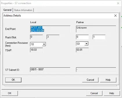
Step 9: Complete the Address Details to exactly match those on the Partner side of the connection.

NetPro View after connection is inserted.

Step 10: In PCS 7, create a Data Block to receive the data.

Step 11: Match the structure that is being sent from TIA Portal.

Step 12: Link the DB to the BRCV block. Enter the number of bytes to be received, please note this is in hexadecimal. Other aspects of this communication may have to be considered. For example, determining when the communication blocks should be enabled, or how quickly should data be sent and received.

Sending data to the TIA Portal skid is done the same way with another pair of BSEND and BRCV blocks in the reverse configuration.
Need Additional Assistance?
Most major PLC, DCS, HMI, and SCADA system vendors recognize ACE as an authorized system integrator. As an independent provider, we can evaluate and work with many different vendor platforms while developing the expertise to interface systems from a variety of vendor platforms into a single, homogenous plant-wide system. More specifically, we are a certified Siemens Solutions Partner for automation drives, which includes both PCS 7 and TIA Portal, and are happy to help customers integrate the latest Siemens technologies into their systems to optimize performance and efficiencies.
Contact us today to see how we can partner with you to develop customized solutions for your systems.
Related Posts
Big changes to PCS7 could affect your system (business?)
PCS7 is Siemens’ flagship DCS system and since its release a couple decades ago it has evolved to...
Your Guide to Integrating Modbus TCP/IP Devices into PCS 7
Today, most modern control systems consist of a variety of hardware and field devices using a range...
Your Guide to Integrating PROFINET Devices into PCS 7
Since PROFINET is the native communication protocol for PCS 7, integrating a PROFINET-enabled...

.webp?width=940&height=491&name=S7%20PLCs%20%20(1).webp)